Helical Pile installation may prove challenging given the many characteristics and specifications that must be met. Given that, we’ve shared our thoughts and best practices below to make sense of it all, help guide the installation, and ensure a competent and confident installation.
Pile load testing is a common and prudent step when installing any type of driven or drilled pile, though one particular type of pile has the potential for self-testing. Small diameter helical piles have a unique advantage when they are being installed, that the installation torque is directly proportional to the ultimate load capacity of the pile. Based on the correlation between the installation torque and load capacity, if you are measuring the installation torque, you should know the ultimate load capacity. So, small diameter (less than 5” diameter) helical piles are self-testing if installed correctly and using a conforming helical pile.
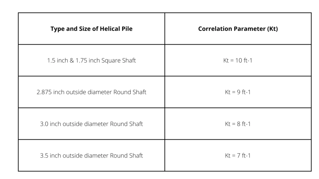
This correlation ranges from a 10:1 to 7:1 relationship, also known as the correlation parameter or Kt. If the Kt is 10, then the Ultimate Axial Capacity (P) equals 10 times the installation torque. The Kt number depends on the size and type of helical shaft as shown in the table below.
P = Kt (ft-1) x Torque (ft-lbs)
The above equation is based upon empirical data and theoretical evidence and is accepted worldwide as an excellent method to determine the load capacity of a helical pile that is installed correctly. This well-supported study performed by Hoyt and Clemence suggests that if a factor of safety of 2.0 is used, there is a 94% probability that measured capacity will be equal to or higher than the predicted capacity based upon torque.
The caveat to this study is that the study was based upon a helical pile with specific characteristics such as:
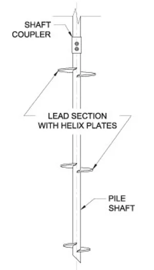
- True helix-shaped plates
- 3” pitch for the helix
- 3/8” thick helix plates
- Helical bearing plates spaced correctly
- Helical plates with diameters of 8” to 14”
Knowing that this study used helical piles with specific characteristics, this capacity to torque correlation should not be applied to all manufactured helical products. Foundation Specialties Geostructural Construction (FSGC) uses only helical piles from manufacturers whose helical piers are independently tested and evaluated by ICC Evaluation Service to the AC358 Acceptance Criteria. This acceptance criteria align with the Hoyt & Clemence study and confirms the following capacity to torque correlation parameter for helical piles evaluated:
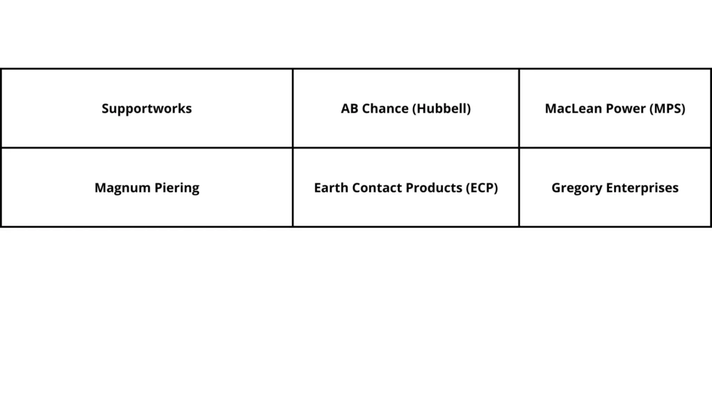
Listed below are some of the manufacturers that have submitted their helical piles to be evaluated and approved by ICC Evaluation Service to the AC358 Acceptance Criteria and have published reports:
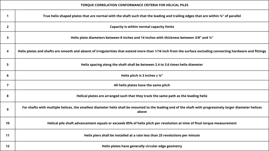
The table below will show some of the criteria that’s evaluated for each helical pier type that the manufacturer has evaluated:
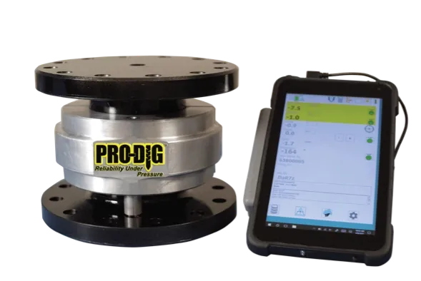
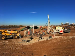
Using the capacity to torque correlation parameter to determine the ultimate capacity of the helical pier works well when you know the direct applied torque to the helical pier when installing. Based upon this fact, FSGC employs the use of an inline torque transducer when installing helical piles. In addition, to providing the direct actual installation torque, it provides the angle of installation, depth of installation and captures this data continuously as the helical pile is installed. This allows our crews to halt driving the helical pier when the targeted torque is reached and remain sustained and have high confidence that we have reached the ultimate capacity for that pier.
FSGC believes that helical piles do not need to be load tested if:
- An AC358 conforming helical pile is used (See a sample list of manufacturers above)
- Helical pile reaches a minimum installation depth (per design engineer requirements)
- Helical pile is installed correctly per manufactured guidelines by an experienced contractor
- An inline torque transducer is used for each helical pile installed (i.e. Pro-Dig Intelli-tork)
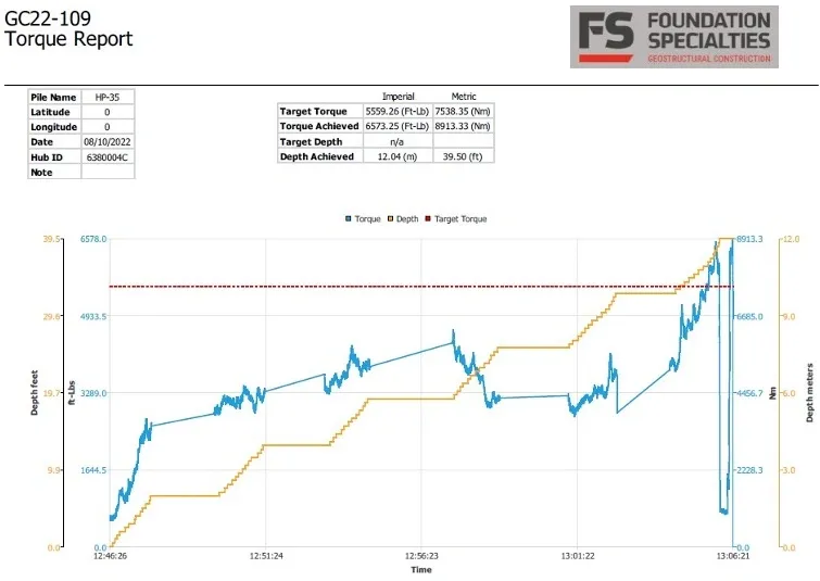
- Closeout documents include an installation report for each helical pile installed showing: depth, target torque, installation torque, and pile number. (see example below)
If any of the items are not provided, FSGC would recommend an ASTM based load test on an installed helical pier.
Below is a typical chart that was produced from the inline torque transducer and provided to our customers.
Red line = Targeted Installation Torque needed to reach Ultimate load capacity
Yellow line = Depth of Helical Pile
Blue line = Actual installation torque